At the cornerstone of every scientific experiment, of course, is the setup which is to be used to collect the data we need. While the MLFilms project intends to produce a working machine learning pipeline which can be adapted and used in a wide variety of experiments in multiple labs, we require a test case experiment on which the system can be tested. We are making use of the Quenching experiment to test our systems and processes on a real case use. For details on what the goals of this experiment are, please refer to the blog post about the XY Model.
Background
Smectic Liquid Crystal (LC) films are formed by discrete layers of molecules. Molecules in the film are largely confined to their own layer but have relatively free movement within their plane giving a 2D liquid behavior. Molecules forming Liquid crystals tend to be long and narrow chains of atoms, and have an orientation concerining what direciton the molecules point.
Smectic C LC films, which are the materials used in this experiment, are interesting in that molecules are orientated in the same direction. The direction of these molecules is the ‘C director’, and reflected light from the film has a polarization along the C director.
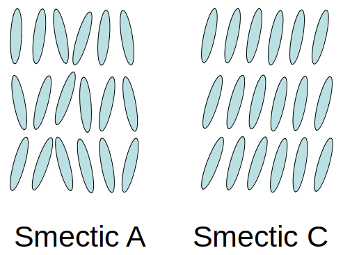 Smectic A films have molecules with random orientation, while molecules in Smectic C films have an orientation consistent with their neighbors
At some points in the film, the molecule orientation may be inconsistent building up to a point where the C director doesn’t line up with the surrounding molecules. These areas where the C director is inconsistent are called ‘defects’. Because of the reflecting light of the film being polarized, defects can be visualized by passing the light through crossed, or partially crossed, polarizers.
The specifics of the defects won’t be discussed in this post, however, it can be stated that defects can have a +1 or -1 ‘power’. Two oposing power defects attract each other and upon meeting will annihilate, eliminating the defects.
In order to generate defects, energy is rapidly added to the film. In this experiment, this will be done by rapidly adjusting the pressures on the two sides of the film.
Requirements of the Setup
For this experiment, we need a setup capable of:
- Consistently generating defects in a film
- Observing defects through partially crossed polarizers
- Tracking pressure differences generating defects during early-time
This setup will need to work on the high-speed camera setup available in our lab, which is currently configured for reflection lighting from the top, with the image being made from the reflected light and the transmitted light through the sample is discarded.
Setup
The image below shows the overall setup used for this experiment.
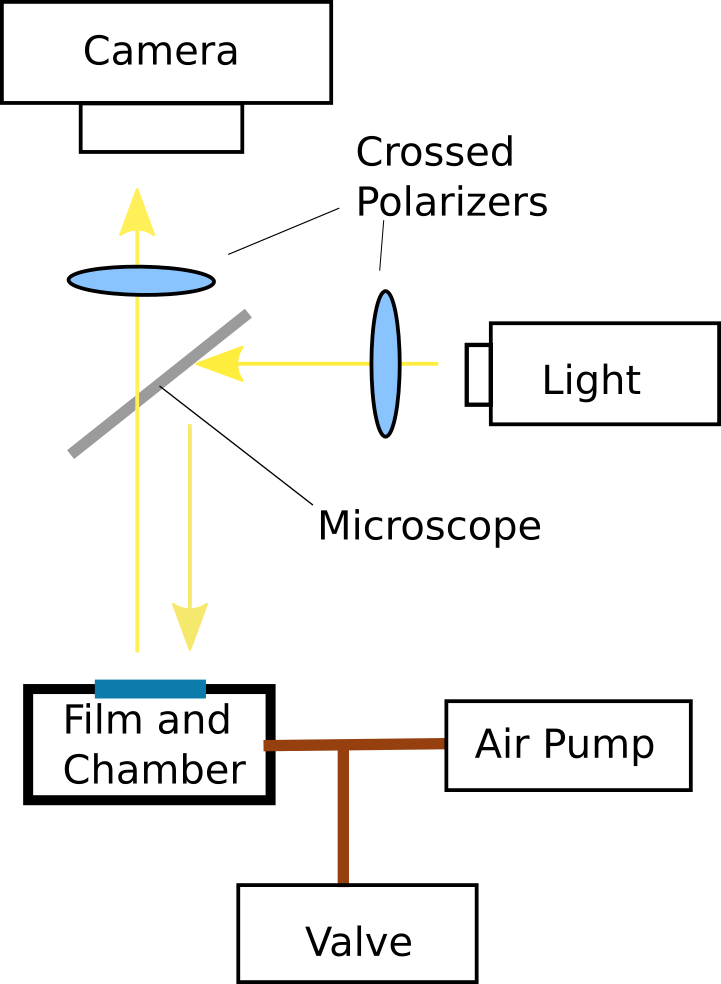 Simple layout of the experimental setup
Films are drawn as a boundary to a pressure chamber, which causes a difference in pressures on the two sides of the film. Upon the pressure difference reaching a specific set value defined on the computer, the pressure is quickly released and the film relaxes back to its equilibrium state. The sudden decompression allows for defects to be generated in the film.
 Film distorting due to pressure differences before a quench
The pressure is applied to the chamber through a tube which is connected to a quick action valve and a pressure meter. The pressure meter outputs a different electrical voltage according to the relative pressure between the surrounding atmosphere and the internal pressure. The pressure meter is hooked up to a computer which can be set to trigger the camera recording and open the valve at the same time when a specific pressure difference is reached.
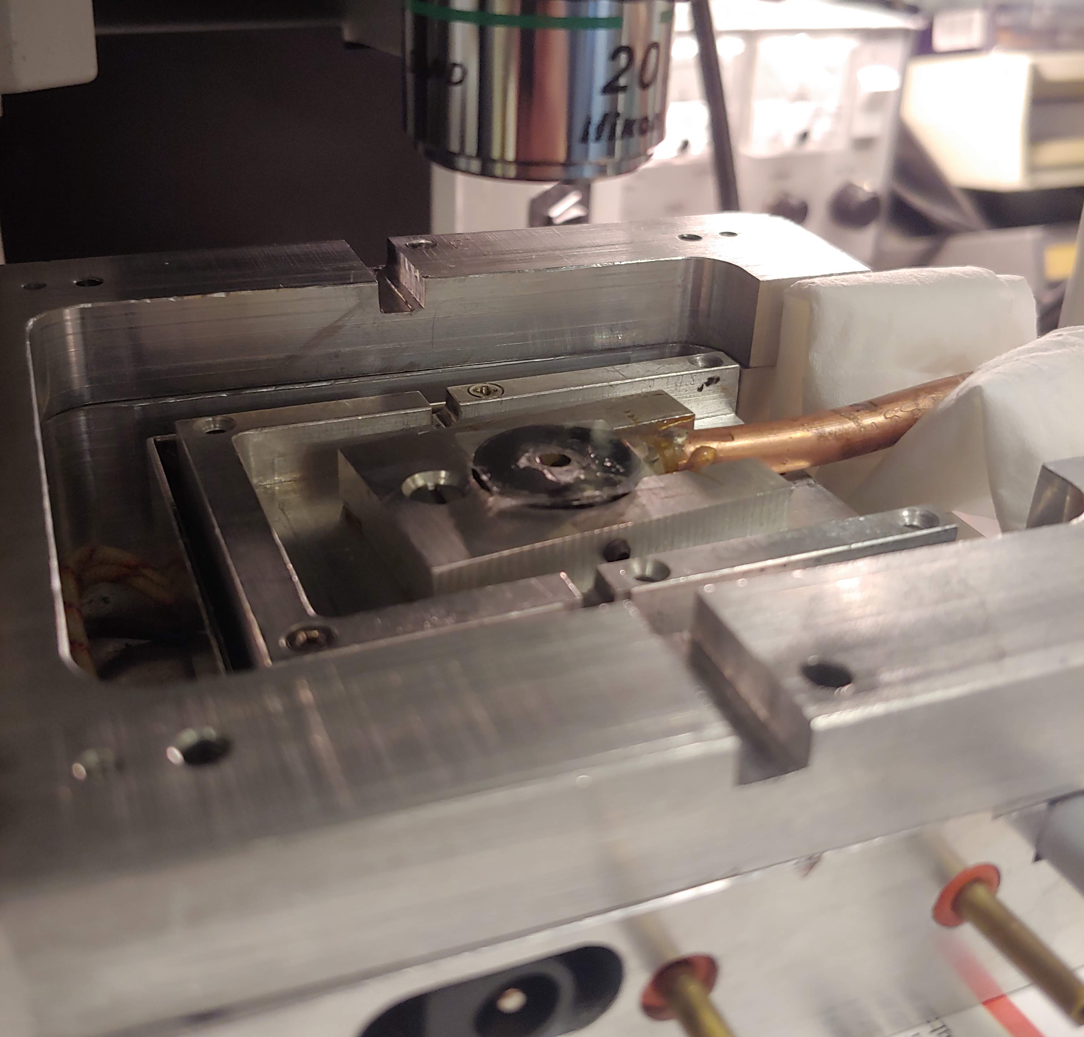 The pressure chamber with the tubing to supply air and the glass slide on which a film is drawn
The pressure chamber is placed inside a heating chamber such that the film temperature can be controlled – if the temperature varies too greatly, the film may change its behavior, and potentially even change its state. For our experiments, the temperature is set to be around 28-36 degrees according to the air flows and temperatures present in the lab on that day.
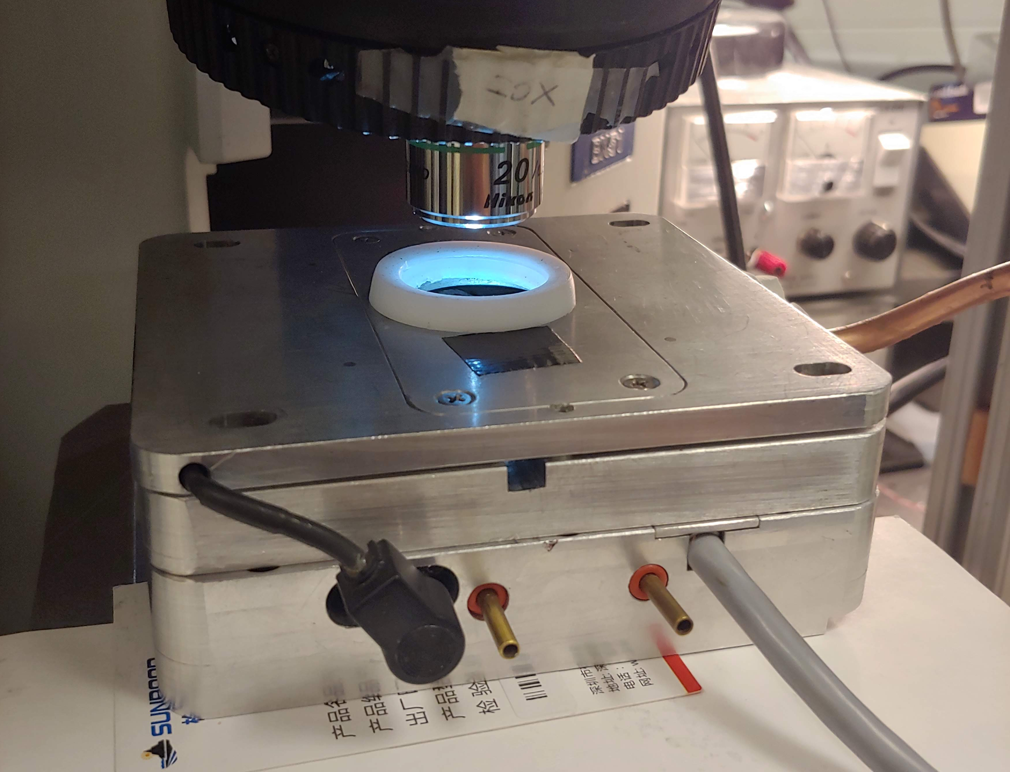 The heat chamber in which the pressure chamber is stored. Copper tube to the right carries the pressurized air, and a 20x objective lens to the microscope observes the film from above.
In order to visualize defects, we shine polarized light onto the film and observe the reflections through a partially crossed polarizer. The light is then captured by a high-speed camera, such that we can observe the defects over a time range.
The high-speed camera used is the Phantom V12.1 grayscale camera. We record at a frame rate of 1000 FPS with 12 bits per pixel images, allowing for a spread of contrast to allow for better contrast alterations in post-processing.
Depending on the film thickness, the polarizer angle varies from around 2-14 degrees off fully crossed in order to allow more light to reach the camera while still maintaining a good contrast to visualize the defects.
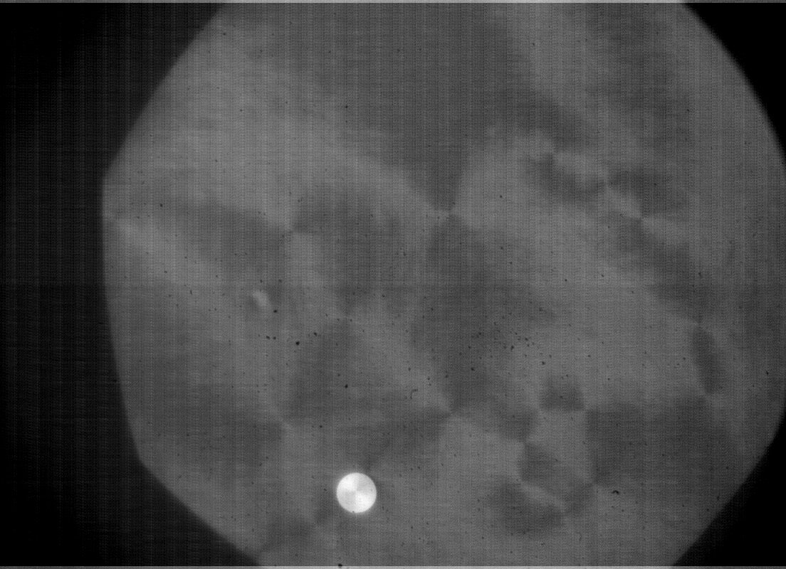 Example image of the film with partially crossed polarizers on the Phantom V12.1
To control the entire setup, a controller program was written in python, with a TkInter Framework. The program constantly reads the voltage from the pressure meter allowing for a constant update of the pressure difference. When a set pressure is reached, the program will send a signal to an Arduino, which controls the valve, to release the pressure, send a ‘trigger’ signal to the camera to start recording images and save the pressure values.
An entire quench run takes about 6 seconds, saving a little over 6000 image frames (about 7-8GB of data), and 200 pressure measurements with their respective time stamps. The data is then saved over the next 10 minutes before the next measurement is made.